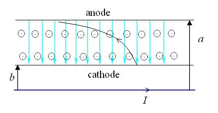
I take that the radius b of the anode is less than the radius a of the cathode. Its easy to verify that the motion of the electron will be confined to a single plane. It is this plane that I show in the figure below:
The solid line represents the path of the electron. The blue lines represent the electric field (it is not uniform though the diagram may suggest that) and the circles dots represent the magnetic field. If the applied voltage is too large, the magnetic field won't be able to path sufficiently and the electron will hit the anode while if its too small the velocity won't increase sufficiently before the electron's path bends back to the cathode. So there is a least value of the voltage at which the electron's path will just graze the anode before bending back. Lets denote this voltage as Vmin. By the time the electron reaches the anode, its speed will become v0 where
eVmin = 12 mv02 ---------- (1)
Next consider an inertial reference frame K which moves with speed v0 (the same as obtained from (1)) towards the left in the figure above. In this reference frame, the total electric field will be
\vec{E}' = \vec{E}+\vec{v}_0\times \vec{B}
where E is the electric field in the wires reference frame while the term \vec{v}_0\times \vec{B}
is additional. This excess term has a magnitude dependent on the distance r from the filament and is equal to v0μ0I2πr. This electric field is in the opposite direction to the field E arising due to the applied voltage Vmin and it will cause a voltage \dfrac{v_0\mu_0I}{2\pi}\ln\left(\dfrac{a}{b}\right) to appear across the anode and cathode which is in opposition to the applied voltage Vmin.
In the reference frame K, the electron is seen to be emitted with a speed v0 parallel to the filament and just at the anode comes to rest momentarily. Hence, conserving energy, we get
\dfrac{1}{2}mv_0^2 =\dfrac{ev_0\mu_0I}{2\pi}\ln\left(\dfrac{a}{b}\right)-eV_\mathrm {min}
Since, from (1),
eVmin = 12 mv02
the above equation becomes
eV_\mathrm{min} =\dfrac{ev_0\mu_0I}{2\pi}\ln\left(\dfrac{a}{b}\right)-eV_\mathrm {min}
That is
V_\mathrm{min} =\dfrac{v_0\mu_0I}{4\pi}\ln\left(\dfrac{a}{b}\right)
Squaring and using (1), we get
V_\mathrm{min}^2 =\dfrac{2eV_\mathrm{min}}{m}\left(\dfrac{\mu_0I}{4\pi}\right)^2\ln^2\left(\dfrac{a}{b}\right)
which finally yields
\boxed{V_\mathrm{min} =2\dfrac{e}{m}\left(\dfrac{\mu_0I}{4\pi}\right)^2\ln^2\left(\dfrac{a}{b}\right)}
as the required least voltage.
A system consists of a cylindrical anode of radius B and a coaxial cylindrical cathode of radius A . A filament located along the axis of the system carries a heating current I . Find the least potential difference between the cathode and anode at which the electrons emerging at zero speed just reach the anode .
-
UP 0 DOWN 0 0 1

1 Answers
kaymant
·2010-08-29 23:00:51